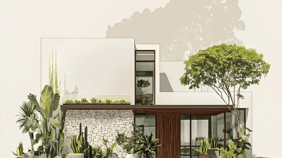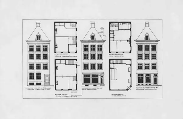
A building elevation drawing helps you understand how a building will look from the outside before construction begins. It shows the exterior appearance of a house or building, including its walls, windows, doors, roofline, balconies and other architectural features. For homeowners planning a new house in Hyderabad, understanding these drawings can make discussions with an architect clearer and help them make informed design decisions.
Unlike a floor plan, which shows the arrangement of rooms from above, an elevation drawing presents a vertical view of a building from a particular side. It communicates the proportions, heights, exterior finishes and relationships between visible elements.
Whether you are planning an independent house, a duplex, a villa or a residential community, learning to read these drawings helps you understand the proposed design and identify important details before construction starts.
What Is a Building Elevation Drawing?
A building elevation drawing is a scaled architectural drawing that represents the exterior face of a building as viewed from a specific direction. It illustrates the vertical arrangement of architectural elements, showing how different parts of the structure relate to one another.
Architects typically prepare elevations for the front, rear and both sides of a building, depending on the project requirements. These drawings help homeowners, architects, structural engineers and contractors understand the intended external appearance.
For example, a front elevation may show the main entrance, windows, balcony railings, facade materials and roof profile. A side elevation may reveal the building’s depth, side windows, floor levels and overall height.
Elevation drawings are also useful for checking whether the exterior design aligns with the requirements of the project, site conditions and applicable building regulations.
What Are the Different Types of Building Elevation Drawings?
Each elevation provides a different view of the building. Together, they offer a more complete understanding of its exterior design.
1. Front Elevation
The front elevation shows the building from the front, usually the side facing the main entrance or street.
It may include:
- Main entrance and entrance porch
- Windows, doors and balconies
- Exterior wall finishes and facade patterns
- Floor levels and roofline
- Decorative elements and shading features
This drawing is particularly useful for understanding the building’s street-facing appearance and overall architectural character.
2. Rear Elevation
The rear elevation shows the exterior at the back of the building. Depending on the layout, it may include utility areas, kitchen windows, service doors, balconies and openings that face the backyard.
It helps the design team coordinate rear access, window placement and the visual appearance of less prominent sides of the property.
3. Side Elevation
Side elevations show the building from its left or right side. They help explain the building’s depth, wall heights, roof slopes, side windows and the relationship between different floor levels.
For plots with neighbouring buildings, narrow side setbacks or uneven ground levels, these views can be especially useful when reviewing openings and exterior design.
4. Sectional Elevation
A sectional view is different from a conventional exterior elevation. It shows the building as though it has been cut vertically through a selected area, revealing internal relationships such as floor-to-floor heights, staircases, ceiling levels and roof construction.
Sections complement exterior elevations by explaining details that cannot be fully understood from the outside alone.
What Information Does an Elevation Drawing Show?
An architectural elevation communicates several details that help translate a design concept into a coordinated construction proposal.
Building Height and Floor Levels
Elevation drawings often include level markers and dimensions indicating ground levels, floor levels, sill heights, lintel heights and roof levels.
These measurements help the project team understand the vertical arrangement of the building. However, the exact information shown depends on the drawing’s purpose and level of detail.
Doors and Windows
The drawing shows the visible positions, proportions and alignment of doors and windows. It can help you assess whether openings are balanced across the facade and whether their placement supports the intended architectural style.
Detailed window and door schedules may be provided separately to specify sizes, materials, hardware and other requirements.
Roof Design and Parapets
The roof profile, parapet walls, overhangs and other visible roof elements may appear in an elevation. These details help communicate the building’s overall silhouette and how the roof meets the exterior walls.
For sloping roofs, the drawing may show the roof pitch or relevant levels, while detailed roof drawings provide additional construction information.
Exterior Materials and Finishes
Architects may use notes, symbols, hatch patterns or finish labels to identify materials such as stone cladding, textured plaster, exposed brick, glass and metal screens.
The drawing may communicate the intended finish, but a separate material schedule or specification is often needed to confirm product details, colours, thicknesses and installation requirements.
Dimensions and Annotations
Dimensions and annotations explain the intended size and position of selected elements. They may identify overall building heights, opening sizes, offsets and other important measurements.
Always refer to the written dimensions rather than estimating measurements from the apparent size of objects on the drawing.
How to Read a Building Elevation Drawing Step by Step
You do not need professional drafting experience to understand the basic information in an elevation. Start with the following steps.
Step 1: Identify the View
Check whether the drawing is labelled front, rear, left or right elevation. Confirming the viewing direction helps you understand which part of the building you are looking at.
If the drawing is part of a larger architectural set, compare it with the floor plan to identify the corresponding side of the building.
Step 2: Check the Drawing Scale
Look for the scale printed in the title block or drawing notes. Architectural drawings may use scales such as 1:50 or 1:100, depending on the sheet size and purpose.
At a scale of 1:100, one unit on the drawing represents 100 of the same units in reality. For instance, 1 cm on a correctly printed drawing represents 1 metre in the building.
Remember that this relationship applies only when the drawing is printed or displayed at its intended scale. If the image has been resized, measured distances may no longer be reliable.
Step 3: Read the Level Markers
Find the level annotations that indicate the ground, floor, roof or other reference levels. These markers help you understand how the building rises vertically.
Check whether levels are measured from a common reference point, such as a designated project datum. Do not assume that every level is measured from the same ground reference unless the drawing notes confirm it.
Step 4: Examine Doors, Windows and Balconies
Look at the position and alignment of openings across the different floors. Check whether windows line up as intended, whether balcony proportions appear consistent and whether the main entrance matches the design you discussed with your architect.
These observations can help you raise questions early, although the elevation alone cannot confirm every functional or structural requirement.
Step 5: Review Material Notes and Symbols
Read the annotations identifying facade finishes, railings, shading devices, screens and other exterior features. If a label or symbol is unclear, refer to the drawing legend, material schedule or related detail drawing.
Avoid assuming that a visual pattern automatically identifies a particular material.
Step 6: Compare the Elevation with Other Drawings
Finally, compare the elevation with the floor plan, sections, structural drawings and relevant schedules.
For example, a window shown on the front elevation should correspond to the appropriate opening in the floor plan. If the drawings appear inconsistent, ask the architect or project coordinator to clarify the discrepancy before construction proceeds.
What Is the Difference Between an Elevation Drawing and a Floor Plan?
Both drawings are essential to understanding a building, but they communicate different information.
An elevation drawing shows the exterior of a building from a particular direction. It helps you understand the building’s appearance, including the facade, windows, doors, balconies, roofline and vertical dimensions. Architects use it to review the exterior design and the proportions of different architectural elements.
A floor plan, on the other hand, shows the layout of a building from above. It illustrates the arrangement of rooms, walls, doors, windows and other spaces. It helps homeowners understand how rooms connect, how people move through the house and how the available space is organised.
For example, an elevation drawing can show how the front of a house will look, while a floor plan explains where the living room, kitchen, bedrooms and bathrooms are located.
Both drawings work together to provide a clearer understanding of the proposed design. For a complete picture of a building, review the elevation alongside the floor plan, sectional drawings and relevant construction details.
Why Are Elevation Drawings Important Before Construction?
Elevation drawings allow homeowners and project teams to review the exterior design before work begins on site.
They help clarify design expectations. Homeowners can discuss the facade, balcony proportions, window placement and entrance design with their architect.
They support coordination. Architects and contractors can use elevations alongside other drawings to coordinate visible building elements and identify inconsistencies that need clarification.
They assist material planning. Facade finishes and exterior features can be identified early, making it easier to discuss specifications, availability and maintenance requirements.
They help assess the building’s context. Exterior views can be considered alongside the plot, neighbouring properties, orientation and site conditions. For larger residential developments, these considerations also connect with long-term residential community master planning, where building placement and the wider site layout influence the overall development.
They support design reviews. Elevations can help the project team examine the proposed exterior against the applicable local development rules. The relevant permissions and compliance requirements should still be verified separately.
An elevation is not a substitute for structural calculations, construction details or statutory approvals. It is one part of a coordinated architectural drawing set.
Common Mistakes to Avoid When Reading Elevation Drawings
Even a well-prepared drawing can be misunderstood if its annotations and limitations are overlooked.
- Estimating dimensions by eye: Always refer to written dimensions and the stated scale.
- Confusing an elevation with a section: An exterior elevation shows a face of the building, while a section reveals what is inside a vertical cut.
- Ignoring level markers: Ground and floor levels help explain the building’s vertical arrangement.
- Assuming finishes are fully specified: A rendered image or hatch pattern may not provide the complete material specification.
- Reviewing one drawing in isolation: Compare elevations with floor plans, sections and schedules to check coordination.
- Using outdated revisions: Confirm that you are reviewing the latest drawing issue approved for the relevant stage of the project.
If you notice a mismatch between drawings, seek clarification from the responsible architect rather than making changes based on assumptions.
How Do Architects Use Elevation Drawings in Residential Projects?
In residential architecture, elevations connect the design concept with the building’s external proportions and appearance. Architects consider factors such as plot dimensions, orientation, neighbouring buildings, privacy, daylight, ventilation and the intended architectural style when developing exterior designs.
For example, a house on a narrow urban plot may require careful window placement and facade articulation to balance privacy with natural light. A villa may need a coordinated approach to balconies, shading, entrance features and exterior materials.
When a project requires coordinated architectural and technical input, a multidisciplinary architecture firm in Hyderabad can help bring the relevant design considerations together. The precise scope of coordination depends on the team, project requirements and appointed consultants.
Homeowners should also remember that a visually attractive elevation must work with the floor plan, site conditions, structural design and applicable building regulations. The best results come from resolving these considerations together rather than treating the exterior as a standalone design.
Frequently Asked Questions
1. What is the main purpose of a building elevation drawing?
Its main purpose is to show the exterior face of a building from a specific direction. It communicates the appearance, proportions, openings, roofline, levels and selected facade details before and during construction.
2. How many elevations are required for a house?
A house may have front, rear, left-side and right-side elevations. The number required depends on the design, project scope, documentation requirements and applicable approval process.
3. Can I understand the building height from an elevation drawing?
Yes. Elevations commonly show vertical dimensions and level markers that help explain the building’s height and floor-to-floor relationships. Refer to the written dimensions and level notes rather than estimating the height visually.
4. Is an elevation drawing enough to start construction?
No. An elevation drawing alone does not contain all the information required for construction. Depending on the project, you may also need coordinated floor plans, sections, structural drawings, service drawings, specifications and relevant statutory approvals.
5. What is the difference between a 2D elevation and a 3D elevation?
A 2D elevation is a flat orthographic drawing showing one side of a building without perspective distortion. A 3D elevation or rendered exterior view communicates depth, materials, colours and visual appearance more realistically, but it may not contain the precise dimensions and annotations required for construction.
Planning a Home That Looks Good and Works Well?
Understanding architectural drawings is an important first step towards making confident design decisions. At Archi Wing Studio, we believe that a well-planned home should bring together exterior appearance, functional layouts and practical design considerations.
If you are planning a new home or residential project in Hyderabad, contact Archi Wing Studio to discuss your architectural design requirements and explore a design approach suited to your plot, lifestyle and long-term needs.